Welcome back to Routing 101.
It’s been a while since the last article went and a lot has happened here at ART in recent months. We have seen some very exciting advances in CNC technology and I have had the privilege of being involved in the research and development for some very unique machines. You will notice we now have a 5-axis High Definition Plasma cutter commissioned and returning some excellent results. And there are of course more projects underway every day.
I have finished the TS01 and have been enjoying the results of the build. Not only is it rewarding to see it all come together but to see the look on the face of everyone that has seen, played and heard the finished product has been inspiring. I will post some sound files when I can get into the studio.
But for now we’ll just step back through the build to the neck design and machining process.
Design…
The neck of a guitar is one of the most important factors to producing a quality, playable instrument. If you get the profile too thin then the neck can be too fragile and you risk a breakage if it ever gets knocked or mistreated. If it’s too thick then it can be too heavy and uncomfortable to play. Then you have to consider the preference of each player. Some will like a C shape profile, others more of a D shape. Then others a V. The width of the neck is also critical for different styles. All up there are a bunch of variables that go into making the perfect neck and the last thing you want is muscle fatigue after a few songs.
I took a fair amount of time assessing my own guitars and any others I could get my hands on to understand what actually makes a comfortable shape and what width suits my style of playing.
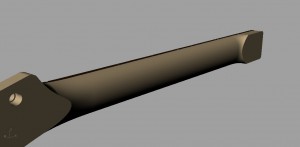
In the end I chose a soft C shape but due to my larger hands and style of playing I made it a little thicker and wider than average. To achieve the correct shape, I used the “digitizing” feature on the SX router. I took a series of templates from an existing neck then placed them flat on the router table. Using the laser fitted to the tool head of the router, I then traced the exact shapes. Once these are displayed on the machine’s pc, I could then export the shapes as DXF’s (Drawing Exchange Format files) to RhinoCad.
Now that I have the profiles I can clean up, modify, rotate and position the shapes accordingly.
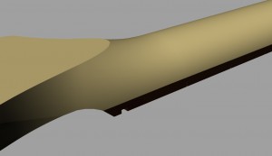
The easiest way to describe the process taken to draw the neck, and any other 3D object, is to imagine a simple 3 view drawing. Each view is placed on top of each other, aligned, then the required profiles are lofted, stretched, swept, and extruded to create the basic shapes. Once the main shapes are in place, you then blend or join the shapes to create the one integral piece. This sounds simple but it takes quite a bit of time to get everything looking perfect. There are many ways to create the one shape so take your time and play around with the different effects you can achieve.
The next step was to draw the truss rod cavity, tuning peg holes, fret and fret marker locations. Once all neck components were drawn, I could then align the neck to the body and check all final measurements.
Machining…
First off I set out all the different pieces of material along with the truss rod and tuning pegs.
Being an organic material, doing a visual inspection of the raw timber is essential to avoid any grain imperfections, cracks or splits. It’s also a good idea to have all components on hand to check tolerances before the job comes off the machine. As mentioned previously, timber can react differently depending on a lot of outside influences like temperature and humidity etc…
A clear advantage of using the ART Profileshop software is that no matter where you place the material on the bed of the machine, you can “align” the job to the material. This comes in very handy when aligning parts to grain or joins and when you need to avoid imperfections in the material. I have also used the “digitizing” feature to trace grain patterns and knots, then import the drawing back to my modeling software so I can see beforehand how the finished product will look.
Having all tools laid out and inspected beforehand is also a good idea. The last thing you want is to be looking for tools half way through a job or having to re-toolpath the job. Basically, forethought is very important to achieve a smooth machining process.
For any 3D machining work I use RhinoCam which is a module of RhinoCad. The two programs work along with each other and make for a very quick and easy to follow package.
I separate the parts and toolpath each piece individually. When machining profiles, I use whats termed an “Endmill” or “Router bit”. For timber there are even more options as referred to in the first article. Normally a traditional straight flute cutter does a great job on timber. For timber with loose grain I tend to lean towards a downward spiral cutter to minimize grain tear. For harder timbers like Maple and Ebony I prefer what is termed a chipper or roughing cutter. This has serrated flutes that break the material being removed into smaller pieces that clear easily. They tend to cut with less vibration and heat as well.
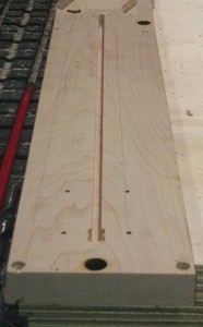
For machining 3D parts, there are a multitude of options. In this case, machining the neck, I first drill the mounting points and locating dowels as per the body. Then once held in position, I machined the truss rod channel in the front of the neck.
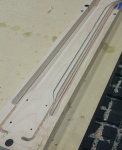
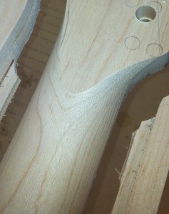
After this was checked for fit, I flipped the material over on the locating dowels and machined the tuning peg holes and Neck mounting holes using a 3mm Endmill. I then moved onto the roughing process using a 10mm Chipper to remove the majority of waste material around the part. You can determine how much material is left around the final shape in the toolpathing software. You can start to see the part really taking shape now.
After the roughing is finished, I used a 10mm Ball nose cutter to do the final surfacing of the neck. In 3D machining, a Round nose or Ball nose cutter is used so that all surfaces can be machined smooth. This is achieved by running back and forth over the surface of the part with a very small overlap and by using Round ended cutter, you can reach all surfaces within a 180Deg. angle. If you can imagine a beach ball rolling over the surface of sand dunes, as the surface changes, the beach ball can make contact with the surface of the dunes until it reaches a vertical wall. Now back to reality, the same process is applied to toolpathing in 3D. Your toolpathing software takes into account the radius of the end of the tool. As the tool travels along the surface of the part, the software will offset the path according to where the end of the tool is making contact with the part. Depending on the settings in your software, this can leave you with a surface that is all but ready for fine sanding.
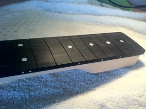
Next up is the Fret Board. I settled on traditional dot markers but instead of using plastic or clay, went for mother of pearl to add a touch of class. Of course any design you could imagine could be utilized given the abilities of our machines but I wanted the finished design to reflect a refined approach. At least this time round anyway….
The Fret Board itself is made from Ebony which is very dense. Because of the tendency to chip and fracture, I used a cutter that was designed for composite materials like carbon fibre. This tool doesn’t have a flute as such but has a series of cutting edges and more resembles a Burr as used in a Die Grinder. Each cutting edge is very small and resists pulling too much material away at any one time. The results turned out perfectly. After all the pieces are done they are sent to a Dimensional Inspection Lab to make sure that they are all correct.
So there we have the neck and Fret Board cut out. The pickups from Kinman Guitar Electrix turned up about this time in a little velvet lined box. Time for some shameless promotion. I first heard Chris’s pickups in the late 90’s and have never heard anything sound as good since. They were the only choice as far as I was concerned and could not be happier with the quality of the components and the sound they produce.
In the next article I will take you through the process of machining the Pickguard and show you a little more of how the guitar turned out and give you more of an insight into the assembly of the guitar. Stay tuned…………
Share

