A guitar is born – Part II
by Greg White
With 3D type work becoming more and more common, I thought it would be fitting to make some samples of what our machines can do and what better way achieve this than to apply this technology to one of the oldest crafts known to man and one that I personally am very passionate about, that of musical instrument making.
Part I described some steps of the process from start to finish – now we go into more detail:
Desgin
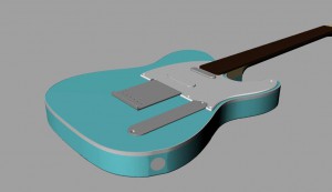
I started out taking photos and measurements from my own guitars, then starting from scratch in RhinoCad, a program especially developed for 3D modelling, I started the design process. A set of critical dimension guidelines were laid out then looking from the top and sides, a basic 3 view outline was drawn. I then used these to extrude the various parts that make up a guitar.
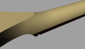
From there, multiple cross sections were taken to give me the final shapes needed to be able to use the Loft, Sweep rails, Blend surfaces and Boolean operations to end up with the desired result. This of course takes time and after starting I learned very quickly that the neck of a guitar is one of the most difficult shapes to create accurately because of all the organic surfaces and complex curve radii.
The end result is what looks like a familiar shape guitar to many but with many subtle differences to accommodate my own taste.
Machining
Now, down to machining. It is important to remember that with timber, every piece is different. The machining characteristics change with each different species. Grain structure, density, abrasiveness and resin retention all have an impact on the finish of the piece. Especially important to consider when doing anything with timber is that it takes on moisture with different weather conditions and then can change size accordingly. So any tight tolerance parts may fit when first machined but if left in humid conditions may become too tight after a period of time. The opposite is also true when timber dries out and shrinks back.
Other crucial factors to consider with machining is the tool used as well and feed rates and direction of cut. When it comes to tool type, there have been many new advancements made in recent times. Having said that, we are all at the mercy of certain rules that apply to organic materials. Grain tear is the first we will consider.
Grain tear occurs when the cutting edge of your tool pulls away part of the timber before cutting through it cleanly. You will notice that this happens usually more so on one side of the cut then the other. This is purely because of the orientation of the blade as it slices through the timber. When using the same tool at the same feed rates but coming from the opposite direction, you will notice that the good side of the cut changes. This is one of the many simple tricks to keep in mind when processing timber. A few moments taken to think about the cut direction verses the grain direction will result in a much better quality cut and also less time for you to be cleaning up what hopefully isn’t damaged beyond repair.
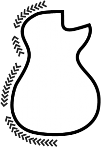
When looking at the spindle from above, it should spin in a clockwise direction. The orientation of cut when moving will be either having the tool on the left hand side of your part (this is called either Kerf Left or Climb milling) or on the right hand side of your part (Kerf right or Conventional milling). With a standard straight or up cut End mill, you need to have the cutting edge of your tool working into your part. See illustration…..
This can prove a bit tricky to understand especially if moving around a shape that has a lot of curves but take the time to think about it and the results are well worth it. It is important to program your tool paths so that you are always cutting into the grain.
Tooling
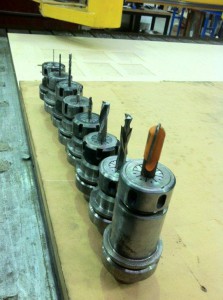
There are a few options to consider with tooling as well. We now have available many different types of roughing or chipping cutters that can be used to take out the majority of material before using a more traditional cutter to clean up the final shape. This means doing multiple passes but these roughing cutters can usually be run a lot faster and tend not to tear as much. They leave a serrated edge to the part which can then safely be cleaned up with a more conventional tool.
We also have the option of using a downward spiral cutter. As the name suggests, these have the cutting edge angled downward. So while the cutter spins in the normal direction the cutting edge is pushing the top surface of the material down first and reducing the tendency to chip or pull timber away from your part. These are ideal when pocketing or trenching but once a full depth cut is required, they can be prone to pushing the bottom surface of your material through with the result of a chipped bottom face.
Another option is what is called a compression cutter. These usually have two flutes or cutting edges but the difference is that each flute is split into two. The bottom of each flute is angled up whilst the top of the flute is angled down. This enables the tool to compress the material into itself without pulling up on the top surface hence giving you a cleaner finish on both surfaces of your part.
From my experience, these work very well and always produce a nice finish. The only down side is that they cannot be run as fast as a conventional cutter because the waste material in effect has nowhere to go. This can generate a lot of heat if not kept in check and result in a burnt edge. When used in conjunction with a roughing cutter however, you can achieve very high feed rates and very clean finishes.
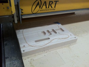
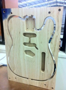
This is the method I used when machining the body of the TS01. After the locating dowel pins and all holes were drilled I proceeded to rough out the shape of the electronic cavities and outer profile with a three flute roughing cutter leaving 1mm around my final shape. This was then cleaned up using a 12mm compression cutter. As you can see the finish is excellent with minimal sanding required before finishing.
Once the front was complete and body still attached to the skeleton, I flipped it over and used the locating dowels to align everything back up while I continued with the back contours. Again I used a roughing cutter then I changed to a 10mm Bullnose cutter to create the final surface for the back contour.
…. to be continued
Share


